Generators are handy gadgets that provide electrical power during a power outage, allowing everyday routines and commercial operations to continue uninterrupted.
Generators come in a variety of electrical and physical layouts to suit a variety of applications.
In the parts that follow, we’ll look at how a generator works, the key components of a generator, and how a generator works as a backup power source in both home and industrial settings.
What Is The Mechanism Of A Generator?
An electric generator is a device that produces electrical energy by converting mechanical energy from an external source.
It’s crucial to realize that a generator doesn’t truly ‘produce’ electricity.
Instead, it utilizes the mechanical energy it receives to push the movement of electric charges existing in its windings’ wires across an external electric circuit.
The output electric current generated by the generator is made up of this flow of electric charges.
This process may be understood by comparing the generator to a water pump, which controls the flow of water but does not ‘make’ the water that passes through it.
The contemporary generator is based on Michael Faraday’s discovery of electromagnetic induction in 1831-32.
Faraday observed that moving an electrical conductor, such as a wire containing electric charges, in a magnetic field may cause the aforementioned flow of electric charges.
This movement generates a voltage differential between the wire’s or electrical conductor’s two ends, causing electric charges to flow and therefore creating current.
#1. A Generator’s Main Components
The following are the key components of an electric generator in general terms:
- Engine
- Alternator
- System of Fuel
- Regulator of voltage
- Exhaust and cooling systems
- System of Lubrication
- Charger for batteries
- Panel of Control
- Frame / Main Assembly
The basic components of a generator are described in the next section.
#2. Engine
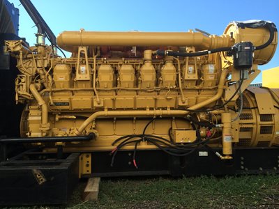
The engine is the source of the generator’s mechanical energy input.
The maximum power output of the generator is directly proportional to the engine size.
While evaluating the engine of your generator, there are a few things to bear in mind.
To receive complete engine operating requirements and maintenance schedules, contact the engine manufacturer.
Type of Fuel Used: Generator engines run on a range of fuels, including diesel, gasoline, propane (liquid or gaseous), and natural gas. Gasoline is used in smaller engines, whereas diesel, liquid propane, propane gas, or natural gas is used in bigger engines. In a bi-fuel operating mode, some engines may run on a dual supply of both diesel and gas.
Overhead Valve (OHV) Engines versus non-OHV Engines: The intake and exhaust valves of OHV engines are positioned in the head of the engine’s cylinder, rather than on the engine block, as is the case with conventional engines. OHV engines provide a number of benefits over other types of engines, including:
- Minimalistic design
- A more straightforward operating mechanism
- Longevity
- Operationally user-friendly
- Operation noise is minimal.
- Low amounts of emissions
OHV engines, on the other hand, are more costly than other engines.
Cast Iron Sleeve (CIS) in Engine Cylinder: The CIS is a cylinder liner in the engine. It lowers wear and tear on the engine and guarantees its longevity. Although most OHV engines include CIS, it is critical to check for this characteristic in a generator’s engine. The CIS is a low-cost feature that improves engine longevity, particularly if you operate your generator often or for lengthy periods of time.
#3. Alternator
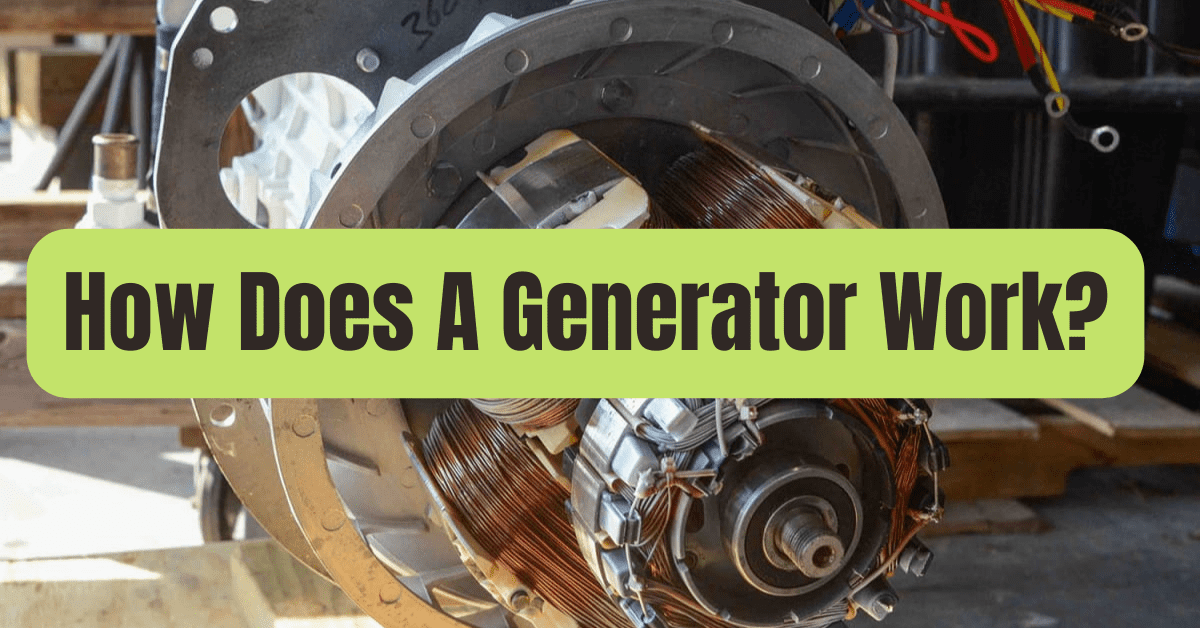
The alternator, also known as the ‘genhead,’ is the component of the generator that generates electrical output from the engine’s mechanical input.
It consists of a housing encasing a collection of stationary and moving elements.
The components work together to create energy by causing relative movement between the magnetic and electric fields.
Stator: This is the component that stays put. It consists of a coil of electrical conductors twisted around an iron core.
Rotor / Armature: This is the component that moves and creates a rotating magnetic field in one of three ways:
By induction: Brushless alternators are utilized in big generators and are termed as such.
By permanent magnets: Small alternator units are prone to this.
By using an exciter: The rotor is energized by an exciter, which is a small source of direct current (DC) that energizes the rotor via an assembly of conducting slip rings and brushes.
The rotor induces a voltage difference between the stator’s windings by creating a moving magnetic field around it.
The generator’s alternating current (AC) output is created as a result of this.
When evaluating a generator’s alternator, keep the following aspects in mind:
Metal versus Plastic Housing: The alternator’s all-metal construction assures its long life. The operating elements of the alternator get exposed when the plastic housings bend over time. This causes more wear and tear and, more importantly, puts the user in danger.
Ball Bearings versus Needle Bearings: Ball bearings are favored because they are more durable.
Brushless Design: Brushless alternators need less maintenance and deliver cleaner power.
#4. System of Fuel
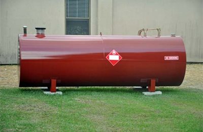
The fuel tank is normally large enough to keep the generator running for 6 to 8 hours on average.
The gasoline tank is either built into the generator’s skid base or positioned on top of the generator frame in the case of compact generator units.
It may be essential to construct and install an external gasoline tank for commercial usage.
All of these installations must be approved by the City Planning Division.
For further information about generator fuel tanks, go to the following page.
The following are some of the most common characteristics of the fuel system:
Pipe connection from fuel tank to engine: The supply line transports gasoline from the tank to the engine, while the return line transports fuel back to the tank.
Ventilation pipe for fuel tank: During the refilling and draining of the fuel tank, a ventilation line is installed to avoid the build-up of pressure or vacuum. To minimize sparks while refilling the gasoline tank, make sure the filler nozzle and the fuel tank make metal-to-metal contact.
Overflow connection from fuel tank to the drain pipe: This is necessary to prevent liquid spills on the generator set if the tank overflows during the refilling process.
Fuel pump: The gasoline is transferred from the main storage tank to the day tank in this way. Typically, the gasoline pump is powered by electricity.
Fuel Water Separator / Fuel Filter: This filters water and foreign debris from liquid fuel to prevent corrosion and contamination of other generator components.
Fuel Injector: This atomizes liquid fuel and sprays the appropriate quantity into the engine’s combustion chamber.
Regulator of Voltage
This component controls the generator’s output voltage, as the name indicates.
The mechanism for each component involved in the cyclical process of voltage control is given below.
Voltage Regulator: AC Voltage to DC Current Conversion – The voltage regulator transforms a tiny amount of the generator’s AC voltage output into DC current. The voltage regulator then sends this DC current to the exciter windings, which are a group of secondary windings in the stator.
Exciter Windings: Conversion of DC Current to AC Current — The exciter windings now create a tiny AC current, comparable to the main stator windings. Units called as revolving rectifiers are linked to the exciter windings.
Rotating Rectifiers: Conversion of AC Current to DC Current – These correct and convert the AC current produced by exciter windings to DC current. This DC current is delivered to the rotor / armature, which generates an electromagnetic field in addition to the rotor / armature’s spinning magnetic field.
Rotor / Armature: Conversion of DC Current to AC Voltage — The rotor/armature now generates a higher AC voltage across the stator windings, which the generator now outputs as a higher AC voltage.
This cycle is repeated until the generator produces output voltage that is equal to its maximum operational capability.
The voltage regulator delivers less DC current as the generator output rises.
When the generator reaches maximum working capacity, the voltage regulator achieves equilibrium and provides just enough DC current to keep the generator functioning at full capacity.
When a generator is loaded, the output voltage drops somewhat.
The voltage regulator is triggered, and the aforementioned cycle starts.
The cycle repeats until the generator output reaches its maximum operational capability.
Exhaust & Cooling System
A/C/Heating/Cooling/Heating/Coo
The generator’s numerous components get heated as a result of continuous operation.
A cooling and ventilation system is required to remove heat generated throughout the process.
Raw/fresh water is sometimes used as a generator coolant, however this is usually confined to certain conditions such as tiny generators in municipal applications or extremely big ones above 2250 kW.
Because hydrogen is more effective at absorbing heat than other coolants, it is occasionally used to cool the stator windings of big generating units.
Hydrogen extracts heat from the generator and transfers it to a secondary cooling circuit using de-mineralized water as a coolant through a heat exchanger.
This is why enormous cooling towers are often seen adjacent to extremely large generators and small power facilities.
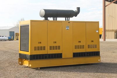
A typical radiator and fan are put on the generator and serve as the main cooling system for all other common applications, both residential and industrial.
It is critical to monitor the generator’s coolant levels on a regular basis.
After every 600 hours of generator operation, the cooling system and raw water pump should be cleansed, and the heat exchanger should be cleaned.
The generator should be located in a well-ventilated, open location with plenty of fresh air.
To guarantee free passage of cooling air, the National Electric Code (NEC) requires a minimum of 3 feet of space on all sides of the generator.
Exhaust System
Generator exhaust fumes include very dangerous compounds that must be adequately regulated, just like exhaust fumes from any other diesel or gasonline engine.
As a result, a sufficient exhaust system must be installed to dispose of the exhaust gases.
This issue cannot be overstated, since carbon monoxide poisoning is still one of the leading causes of mortality in post-hurricane communities, owing to the fact that people don’t think about it until it’s too late.
Cast iron, wrought iron, and steel are the most common materials used for exhaust pipes.
These must be self-contained and should not be supported by the generator’s engine.
To reduce vibrations and protect the generator’s exhaust system, exhaust pipes are frequently connected to the engine using flexible connections.
The exhaust pipe ends outside and leads away from the home or building’s doors, windows, and other openings.
You must guarantee that your generator’s exhaust system is not linked to any other equipment’s.
You should also check local municipal bylaws to see whether your generator operation requires clearance from the authorities.
This will guarantee that you are following local rules and will protect you from fines and other consequences.
System of Lubrication
Because the generator’s engine has moving components, it needs lubrication to maintain long-term durability and smooth performance.
Oil contained in a pump lubricates the generator’s engine.
Every 8 hours of generator operation, you should check the lubricating oil level.
Every 500 hours of generator use, you should check for lubricant leaks and replace the lubricating oil.
Charger for Batteries
A generator’s steart function is battery-powered.
The battery charger maintains the charge of the generator battery by providing it with a precise ‘float’ voltage.
The battery will stay undercharged if the float voltage is too low.
The battery’s life will be cut short if the float voltage is too high.
To avoid corrosion, most battery chargers are constructed of stainless steel.
They’re also completely self-contained, requiring no tweaks or changes to the settings.
The battery charger’s DC output voltage is 2.33 Volts per cell, which is the exact float voltage for lead acid batteries.
The battery charger produces an isolated DC voltage that interferes with the generator’s regular operation.
Panel of Control
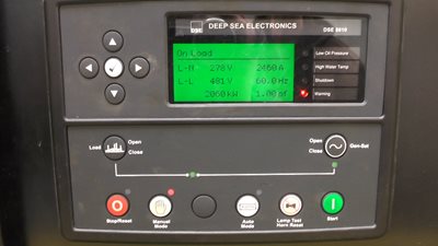
This is the generator’s user interface, which includes accommodations for electrical outlets and controls.
More information on the generator control panel may be found in the following article.
The control panels of different manufacturers’ devices include a variety of characteristics.
A few of them are listed below.
Electric start and shut-down: During a power outage, auto start control panels automatically start your generator, monitor it while it’s running, and shut it down when it’s no longer needed.
Engine gauges: Important information such as oil pressure, coolant temperature, battery voltage, engine rotation speed, and time of operation are shown on several gauges. The generator is automatically shut down when any of these parameters crosses their respective threshold values, thanks to continuous measurement and monitoring.
Generator gauges: Meters for measuring output current and voltage, as well as operating frequency, are included on the control panel.
Other controls: Among the controls are a phase selection switch, a frequency switch, and an engine control switch (manual or automatic).
#5. Frame/Main Assembly
All generators, whether portable or permanent, have unique housings that serve as a structural foundation.
The frame also enables for the earthing of the produced power for safety.

