This page includes affiliate links, just so you know.
At no additional cost to you, I could get a tiny compensation if you decide to buy anything after clicking on one.
I’m going to walk you through every step of setting up your own solar panel system in this video.
It’s true:
I used these identical procedures while building my own solar power system.
Let’s get going.
Materials & Tools
Materials
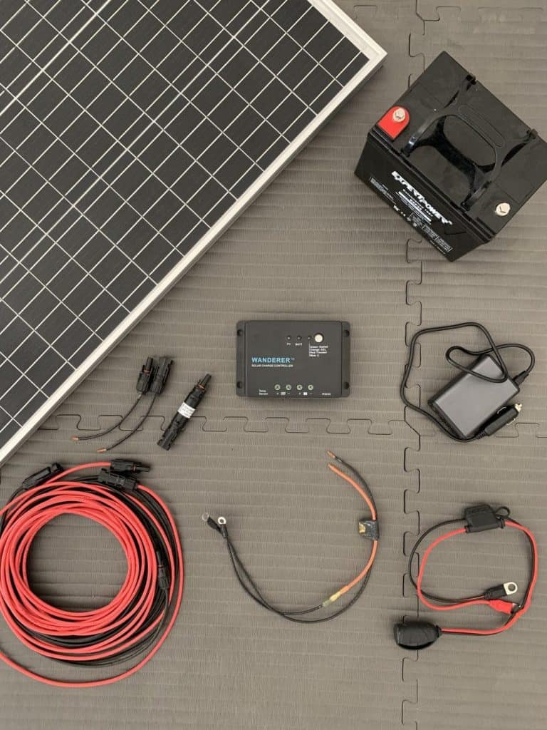
Primary elements:
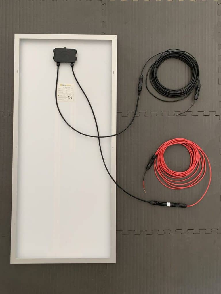
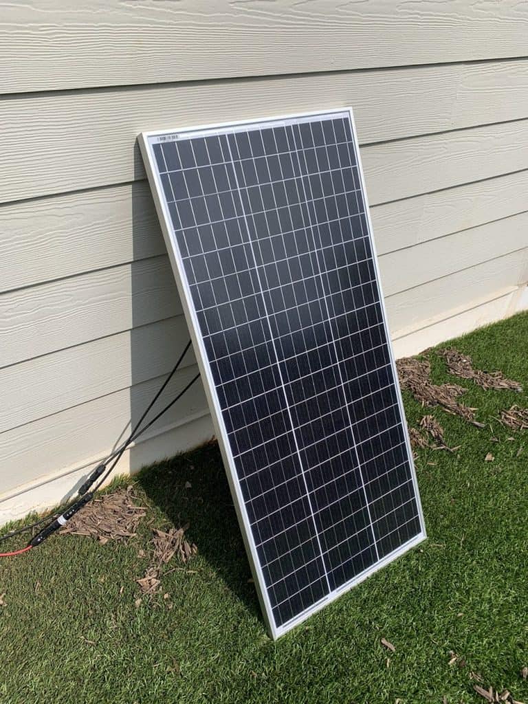
- Newpowa 100W 12V solar panel — or any good 100 watt solar panel
- ExpertPower 12V 33Ah lead acid battery
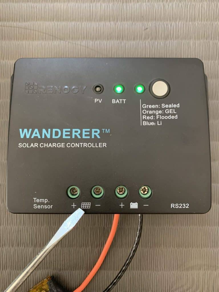
- Renogy Wanderer 30A solar charge controller
- Bestek 150W inverter
Battery charge controller connection:
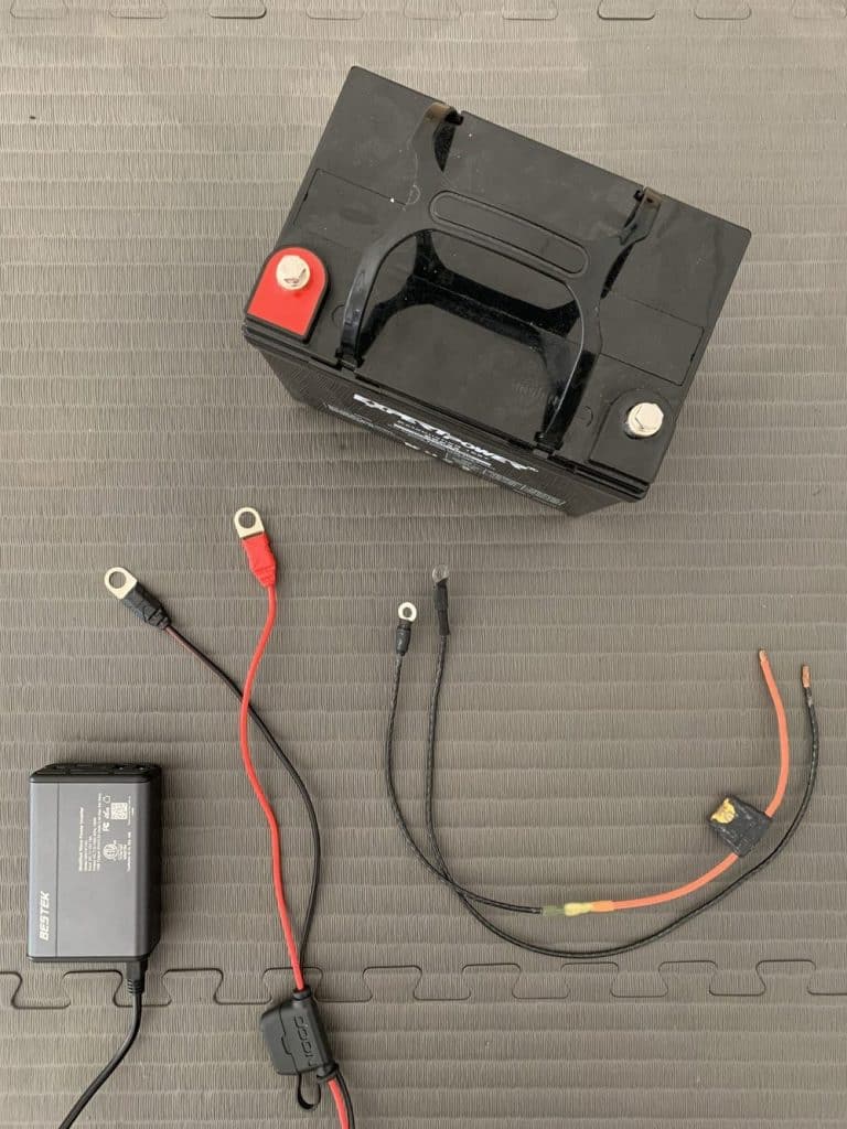
- Option 1: Construct your own battery wires (this is what I did)
- 10 gauge copper wire
- 12-10 ring terminal and butt splice connectors
- Littelfuse inline fuse holder
- 20A blade fuse
- Heat shrink tubing
- Option 2: Invest in premade battery wires (the easier option)
- 10 gauge 8 ft battery to charge controller tray cables
- 20A ANL fuse
Inverter to battery connection:
- NOCO GC018
Solar panel and charge controller connection:
- 10A MC4 inline fuse
- 10 gauge solar panel to charge controller adapter cables
- 10 gauge solar panel extension cables (if needed)
Note: You may replicate my solar panel system exactly as is, or you can change the proportions of the different parts and wire materials to suit your energy requirements.
Tools
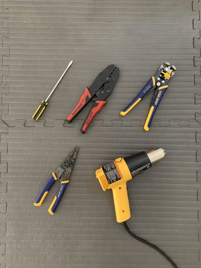
Necessary:
- Screwdriver
When building your own battery wires, just necessary:
- Wire cutter
- Wire stripper
- Wire crimper
- Heat gun
Step 1: Understanding The Solar Wiring Diagram
This system’s wiring schematic for solar panels is as follows:
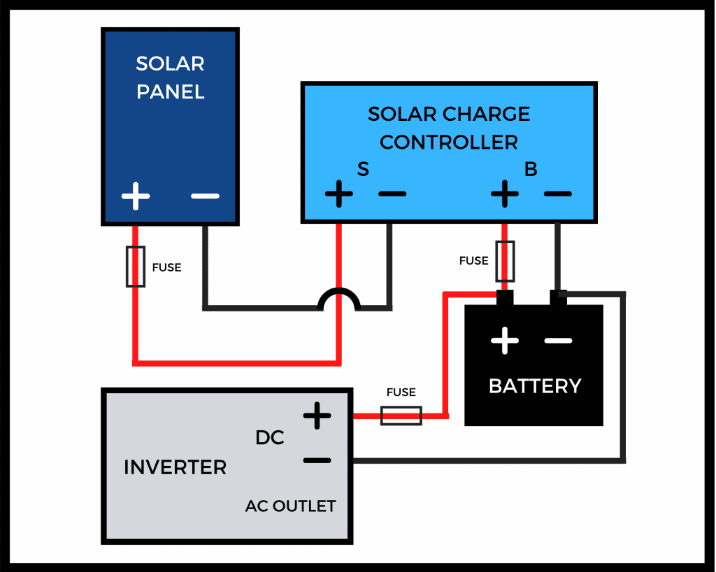
The key concepts to comprehend about it are as follows:
- Four major parts make up a simple solar panel arrangement. A battery, solar panel, charge controller, and inverter are among them.
- Don’t connect the solar panel to the battery directly. This might harm the battery. To properly charge the battery, you must instead connect both to a charge controller that manages the incoming solar energy. Most charge controllers demand that you connect the battery and solar panel in that sequence (and reverse this order when doing disconnections). The suggested installation sequence may be found in the controller’s handbook.
- Each connection on your system should have a fuse to protect it. Put a fuse between the solar panel and charge controller, the battery and inverter, and the battery (on the positive wires of each connection).
- Don’t drain the battery too much. Some batteries don’t have a built-in BMS to guard against overdischarge, such as lead acid batteries. Give yourself some leeway when choosing the size of your battery, and keep an eye on the voltage of your battery using the LED indications on your charge controller.
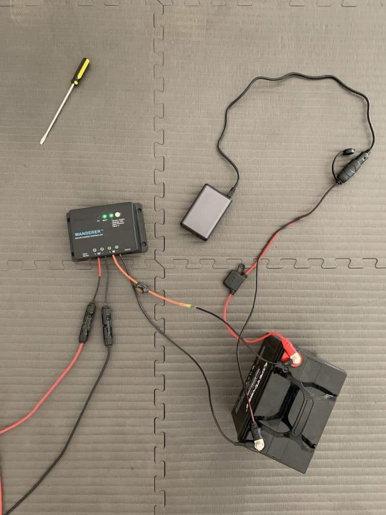
Step 2: Connect the Battery to the Inverter and Charge Controller.
Knowing how the system works presently,
…start constructing now!
If you choose to create your own battery cables, learn how to do so by reading Step 2 of my guide on how to connect a solar panel to a battery.
Bolt the ANL fuse to the positive battery wire if you prefer to use pre-made battery cables.
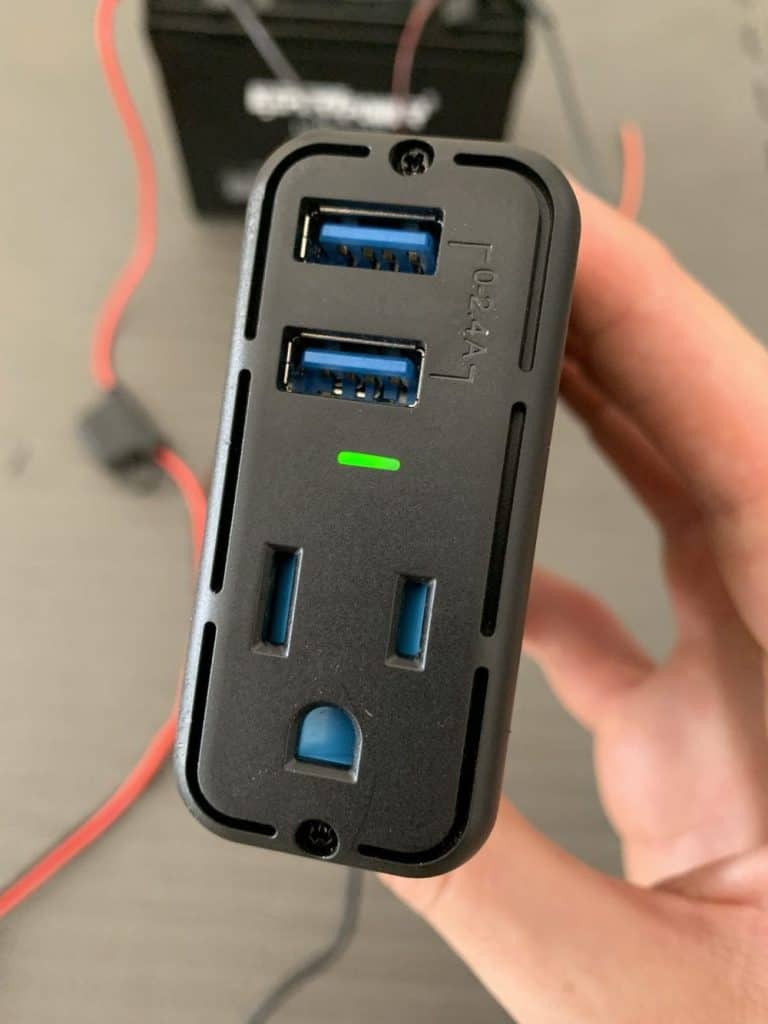
Then, connect the Bestek inverter’s 12V connector to the NOCO GC018’s 12V socket.
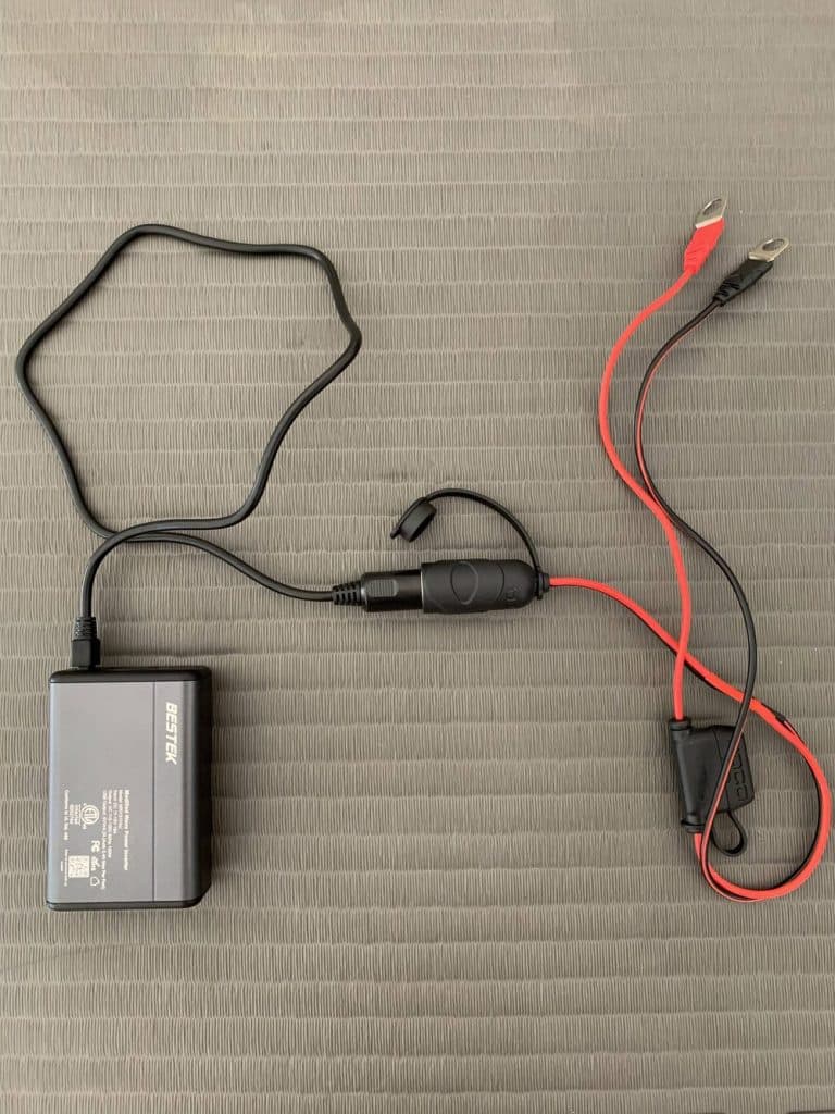
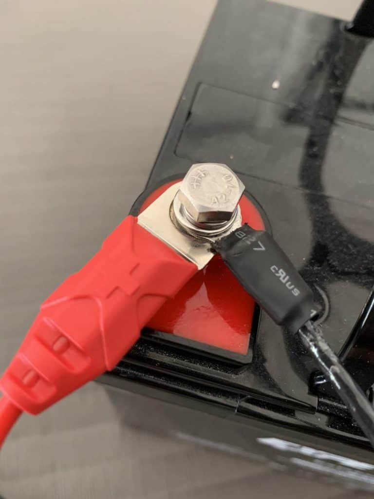
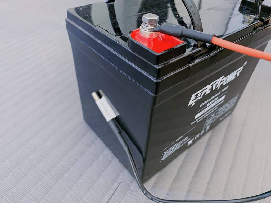
The battery terminals will now be connected to the NOCO GC018 cables and ring terminal connections on the battery cables.
The positive terminal on the battery should receive the positive wires from the inverter and the battery cables.
(I only hand-tightened the terminal bolts.
If necessary, a ratchet may be used.)
The negative battery terminal should receive the negative wires.
(Be sure the charge controller cables’ stripped ends don’t contact in case the battery gets shorted!)
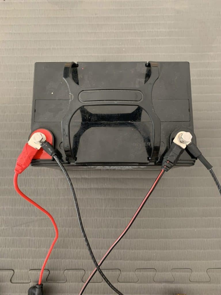
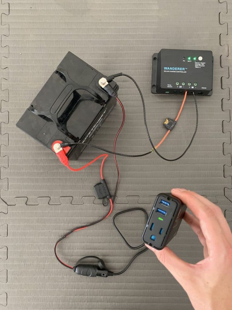
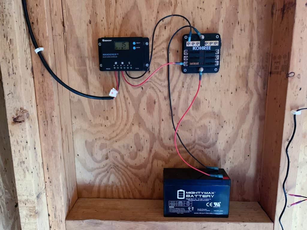
At this moment, the state of my system was as follows:
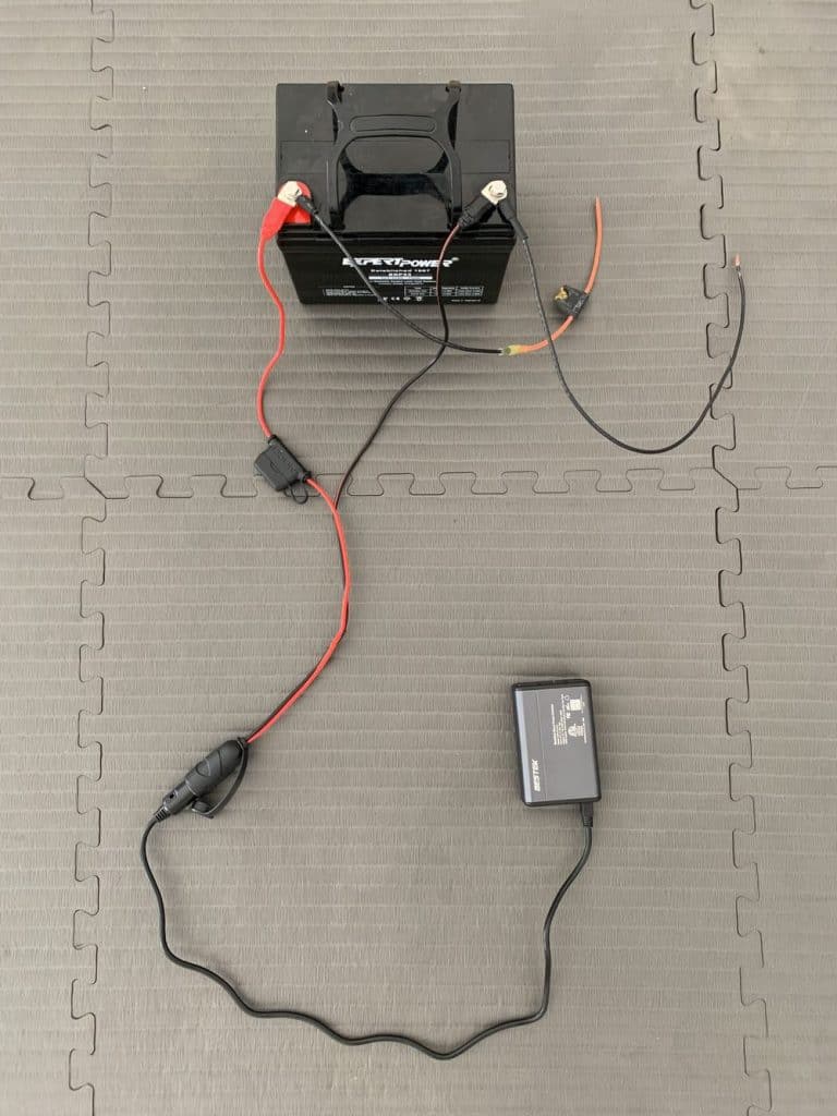
Your inverter and batteries are linked after you have connected both sets of cords.
When an inverter is correctly connected, it will often include an LED indication that illuminates to let you know it is on.
For instance, on mine, a green light came on.
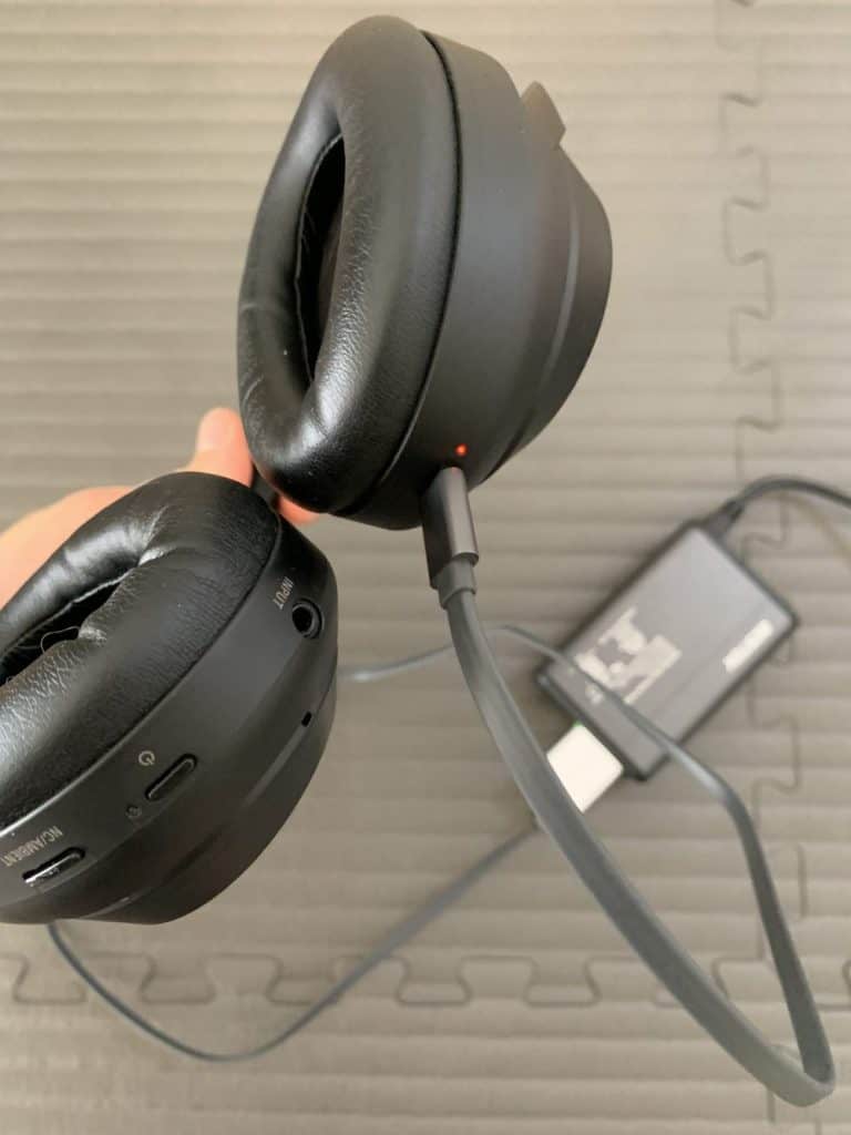
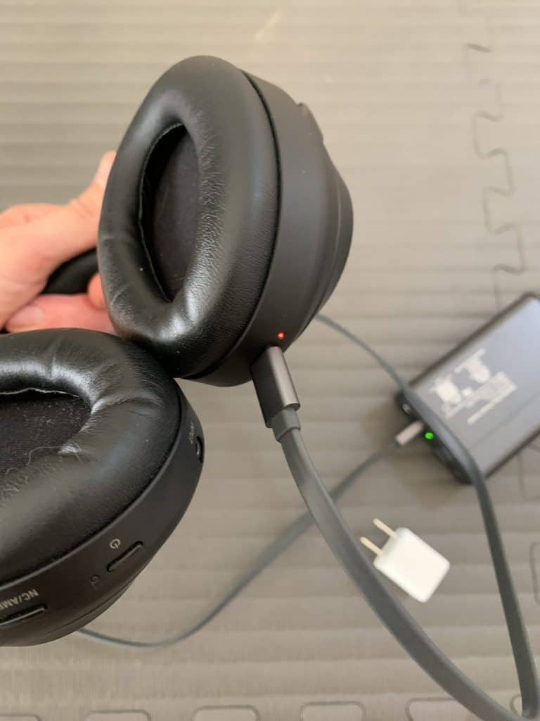
I made the decision to test the inverter first by connecting my wireless headphones to the AC socket using a wall adapter before continuing.
When I did, my headphones’ red light turned on to show that they were charging.
I then connected the headphones straight to the USB port on the inverter.
The red charging light flashed once more.
My inverter works!
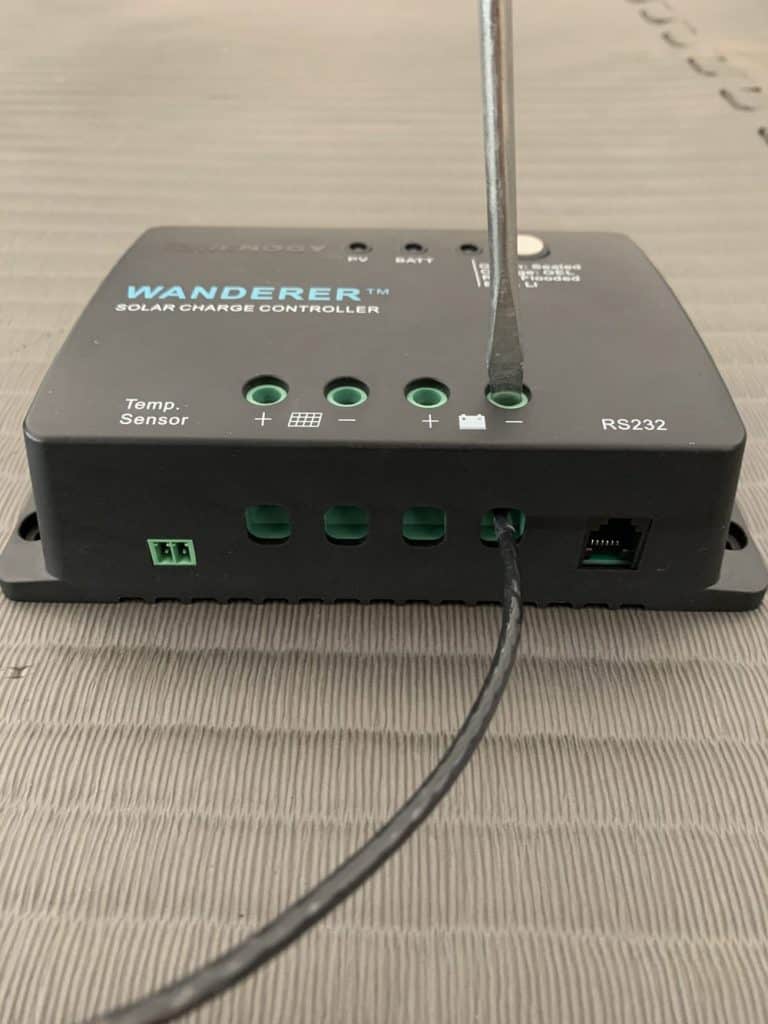
Finish the charge controller connection now.
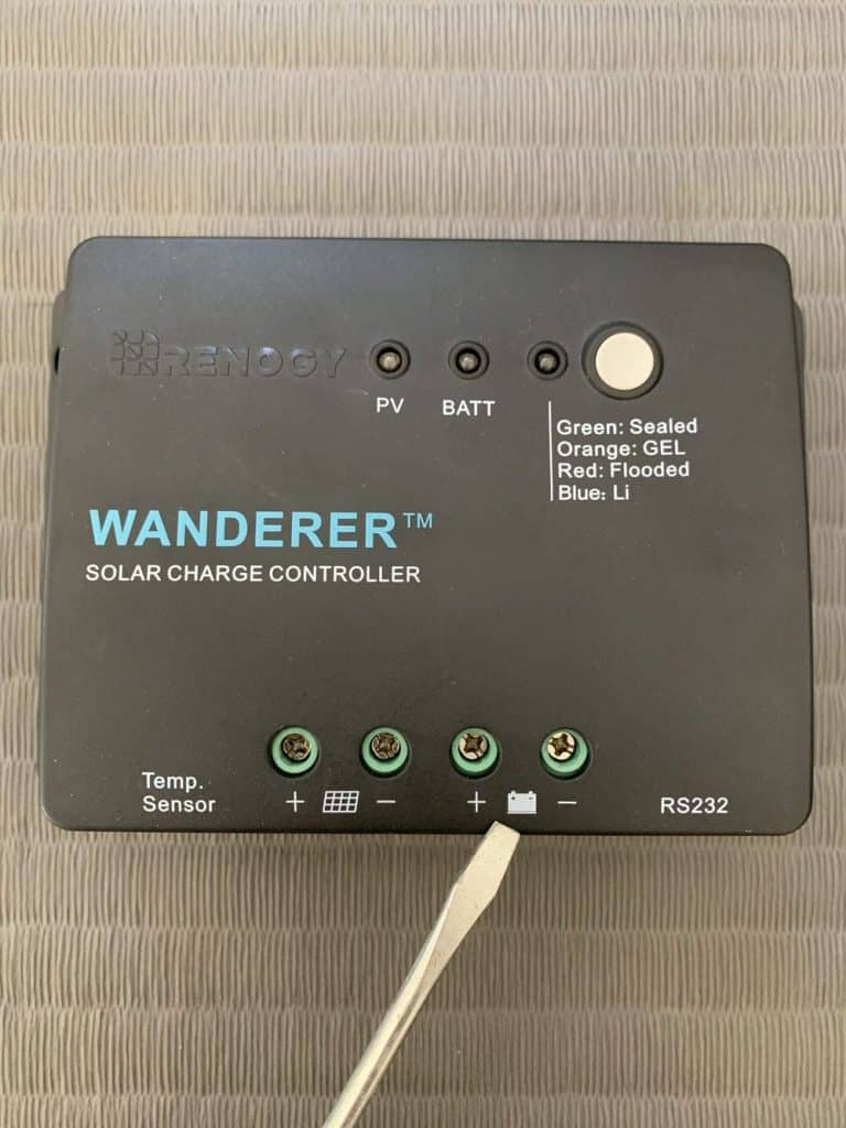
Find the battery terminals on your charge controller first before doing this.
My charge controller, like the majority of others, displays a battery symbol to show them.
Put the stripped end of the negative battery cable into the charge controller’s negative battery connector.
Utilizing a screwdriver, tighten the screw terminal shut.
Note: I’ve found that here, order is not important.
The positive battery wire might potentially be connected first.
I just decided to attach the negative wire first at random.
Make sure the battery cable doesn’t come out by giving it a small twist.
It need to be well sealed.
I repeated this procedure with the positive battery cable to complete the connection between the battery and charge controller.
Its stripped end was placed into the charge controller’s positive battery terminal, and I then used a screwdriver to secure the termination.
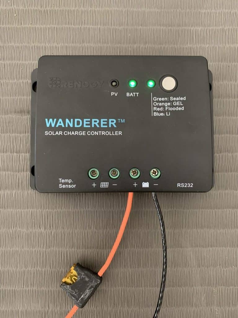
Your inverter and charge controller should be turned on at this time.
My charge controller’s two LED indications flashed up to show that it was connected to the battery correctly.
And as we’ve already seen, my inverter’s green light began to illuminate.
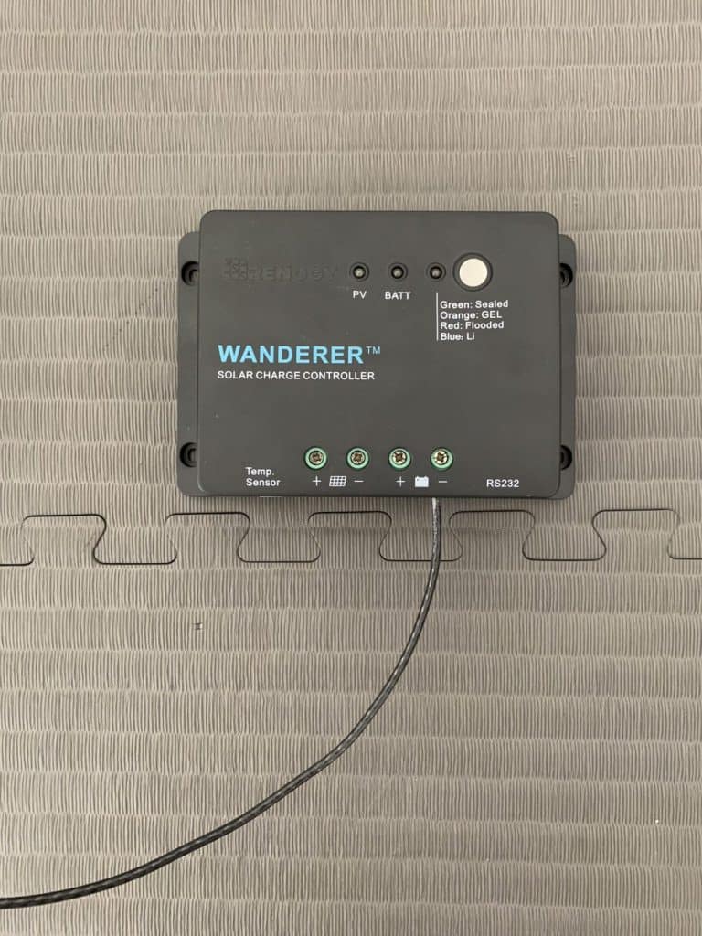
To set your controller for your battery type and voltage, go to the handbook that came with it.
I pressed and held the grey button on my Wanderer 30A controller until the LED began to flash.
I then depressed the button until my sealed lead acid battery’s color code appeared on the LED.
When the flashes ceased, I kept holding the button.
The battery, charge controller, and inverter are all now coupled.
There is just one more item to link at this time:
It’s a solar panel.
Step 3: Connect The Solar Panel To The Charge Controller
Put your solar panel on the ground with its face down (on top of a towel or cushioned surface to prevent scratches).
You’ll have easier access to the panel’s wires and less possibility of being shocked if you do this.
On your solar panel, find the positive solar wire.
I discovered it on mine by looking for the little + symbol on the connection box at the panel’s rear.
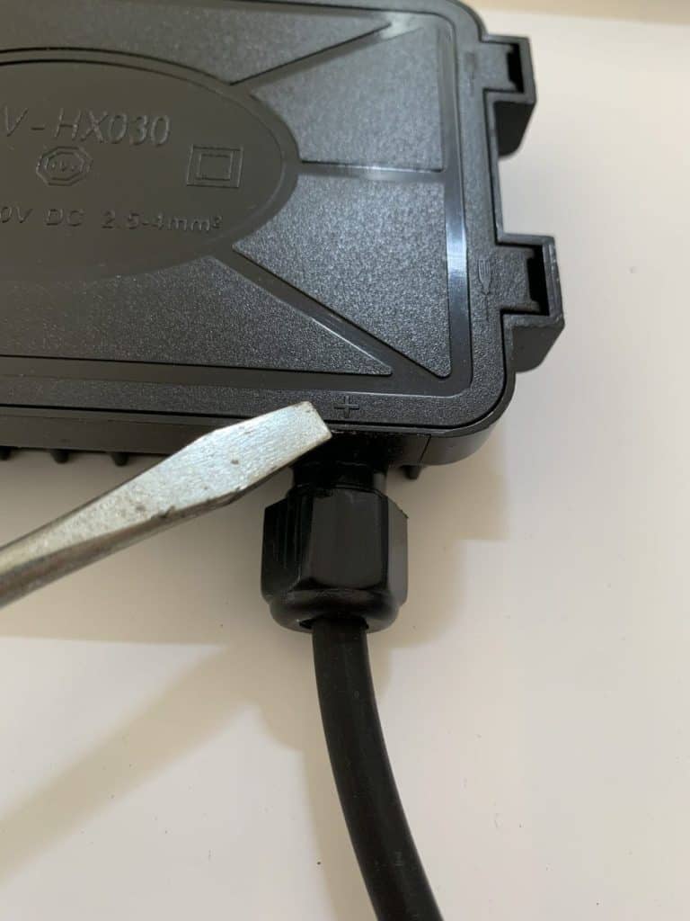
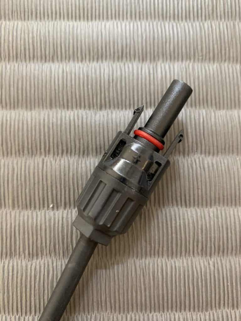
The male MC4 connection, which often has a little plus sign on the connector body and a red rubber ring around it, may also typically be used to locate it.
(The positive wire on every solar panel I’ve dealt with has a male connection on it.)
Connect the positive solar panel connection to the MC4 inline fuse.
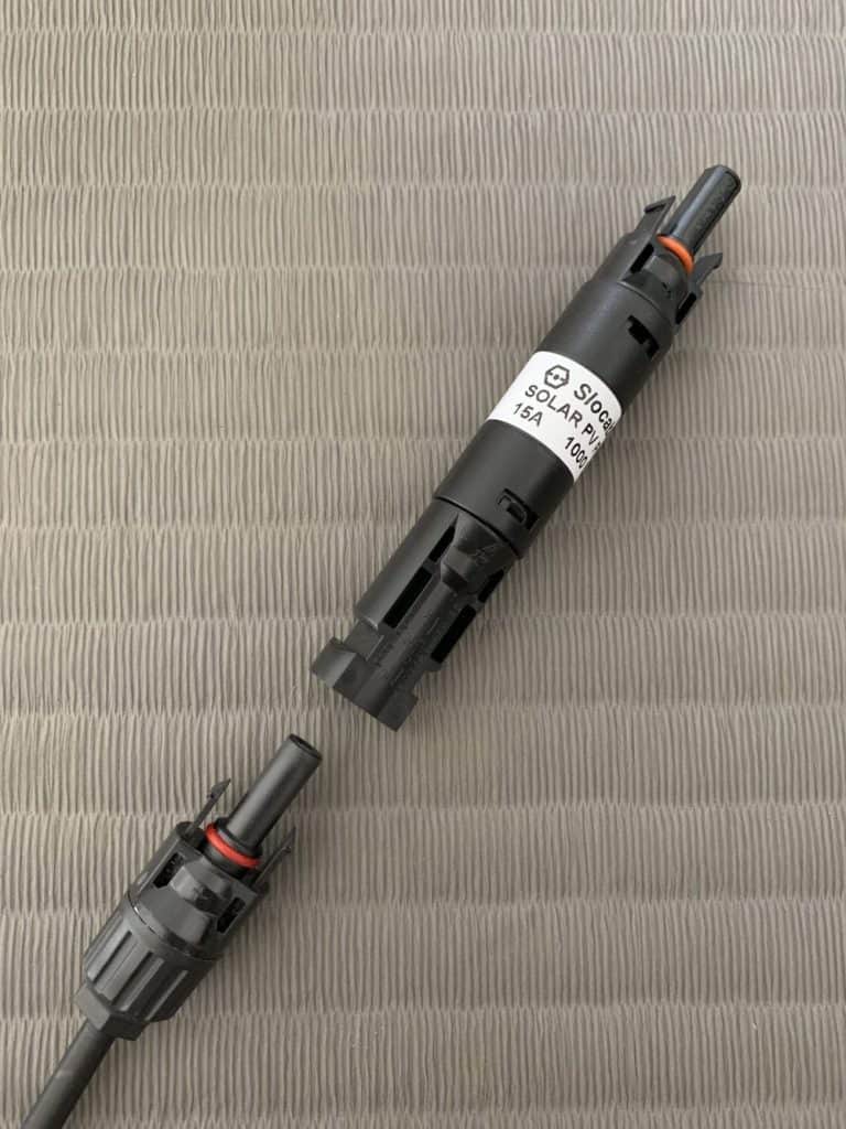
Connect the charge controller adapter cable, positive solar cable, and positive solar extension cable as follows:
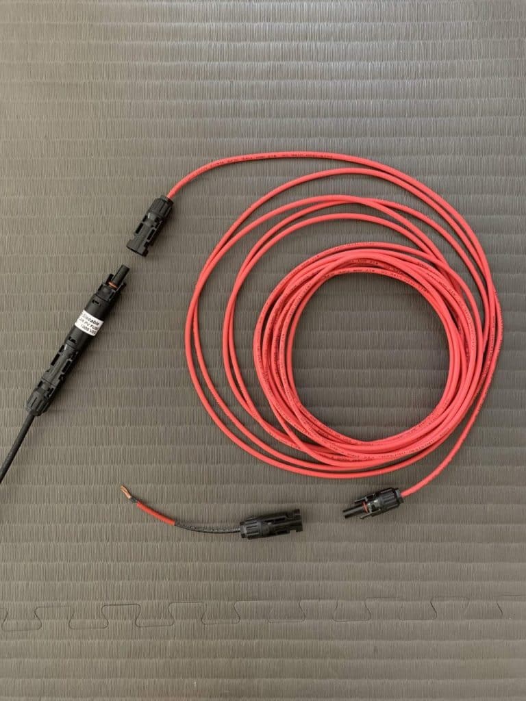
For the negative solar cable, repeat the procedure (excluding the fuse).
In order to link the solar panel cable, extension cable, and adapter cable in my configuration, I did it as follows:
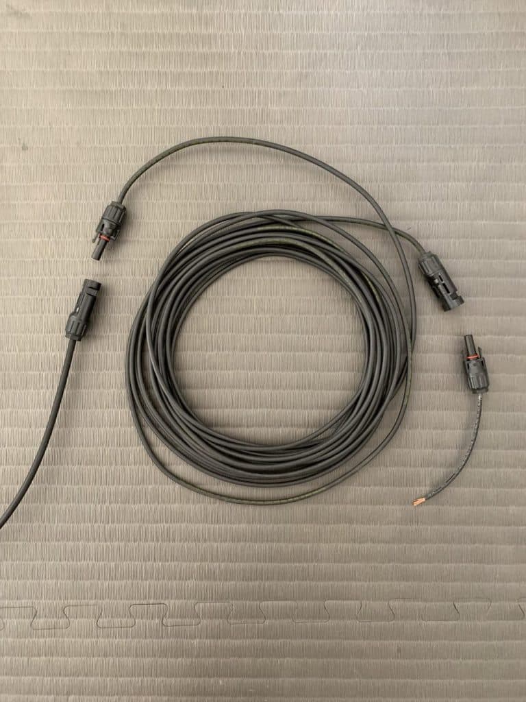
And this is how they appeared when they were joined:
The solar charge controller and solar panel may now be connected!
Find the PV connectors for your solar panels on your charge controller.
Which ones they are is shown on mine by an emblem of a solar panel.
Use a screwdriver to secure the screw terminal after inserting the stripped end of the negative solar cable there.
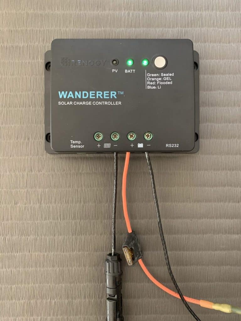
Apply the same technique to the positive solar cable’s stripped end.
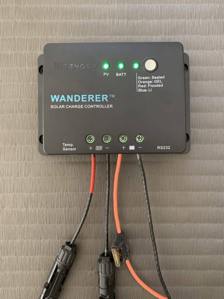
As you can see, after inserting the positive solar wire, my charge controller’s PV indication light illuminated, indicating that the solar panel was connected successfully.
According to the instruction manual, it remained constant green, indicating that the solar panel was not yet recharging the battery.
Since my solar panel was lying face down on the ground, this was to be anticipated.
You just need to place your solar panel out in the sun for it to begin charging your battery.
Step 4: Test Your Solar Panel Setup
Bring your solar panel outdoors, and position it in the sun.
The battery charging status should now be shown on your charge controller.
To alert me that the solar panel was recharging the battery, my PV light began to glow green.
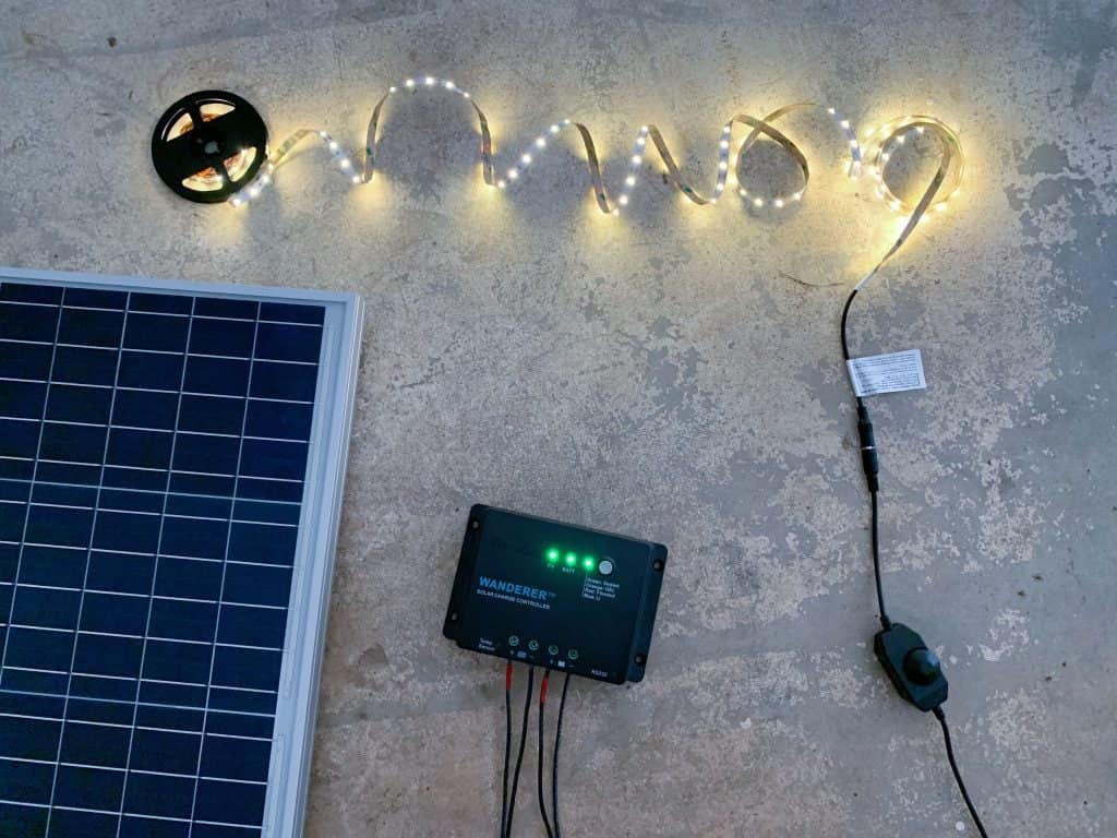
I’ll guide you through my whole solar panel setup in the following video:
The green flashing light indicates that my solar panel is charging my battery, as I previously said.
Nice!
One last look at all the links is provided here:
You have just successfully installed your first solar panel installation.
Because it’s inexpensive, you learn a lot, and it can be used as is or extended in numerous ways, this system is a terrific first solar power project.
How to Install and Operate This Solar Power Device
1. Position the solar panel so that it is tilted at the ideal angle for your site.
You can locate yours and place it anywhere you choose — on the ground, on your roof, or on a wall — by using our solar panel angle calculator or by looking through our list of the greatest solar panel angles by zip code.
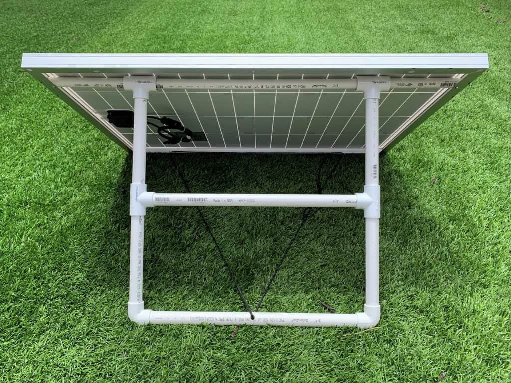
Use our easy DIY solar panel stand as one option.
2. Install the solar charge controller, inverter, and battery inside, maybe in a utility closet or cabinet.
To extend the battery’s life, they should be positioned next to an AC source.
The charge controller and fuse block were wall-mounted when I used solar electricity to power my dad’s shed.
3. Connect your gadgets to the inverter.
For instance, you may put your phone charger straight into a USB socket.
You may use the AC outlet to plug in some lights or a laptop charger.
To avoid overloading the inverter, determine the total wattage of all your gadgets before connecting them.

I’m done now! The battery will be stocked with the free solar energy that the solar panel will have stored throughout the day so that you may use it anytime you choose.
Upgrades and Add-Ons
1. Add LED lights, first.
Energy-efficient and brilliant LED lights are available.
When it comes to solar panel installations, they are ideal.
You may either connect them directly to the battery, like I do in my guide on how to solar power LED lights, or you can link them into the inverter.
2. Include a sensor for battery temperature.
For a more precise battery temperature measurement, you may tape the probe of the battery temperature sensor to the Renogy Wanderer 30A used in this tutorial’s interface.
By modifying its charging conditions depending on battery temperature, the charge controller is able to extend the life of your battery to its maximum potential.
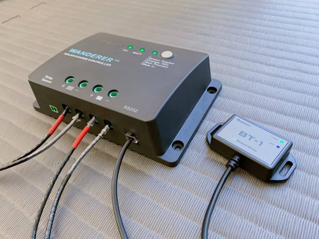
3. Include Bluetooth tracking.
The Renogy BT-1 Bluetooth Module allows you to remotely monitor your solar system from your phone when using a compatible Renogy charge controller.
Connect your phone to it by plugging it into your charge controller and using the Renogy DC Home app.
You may use the app to keep track of system specifications like battery voltage, charging current, and more in real-time.