What You Will Need
- Manufacturer’s manuals
- Ink and paper
- Screwdriver
- Wire cutters
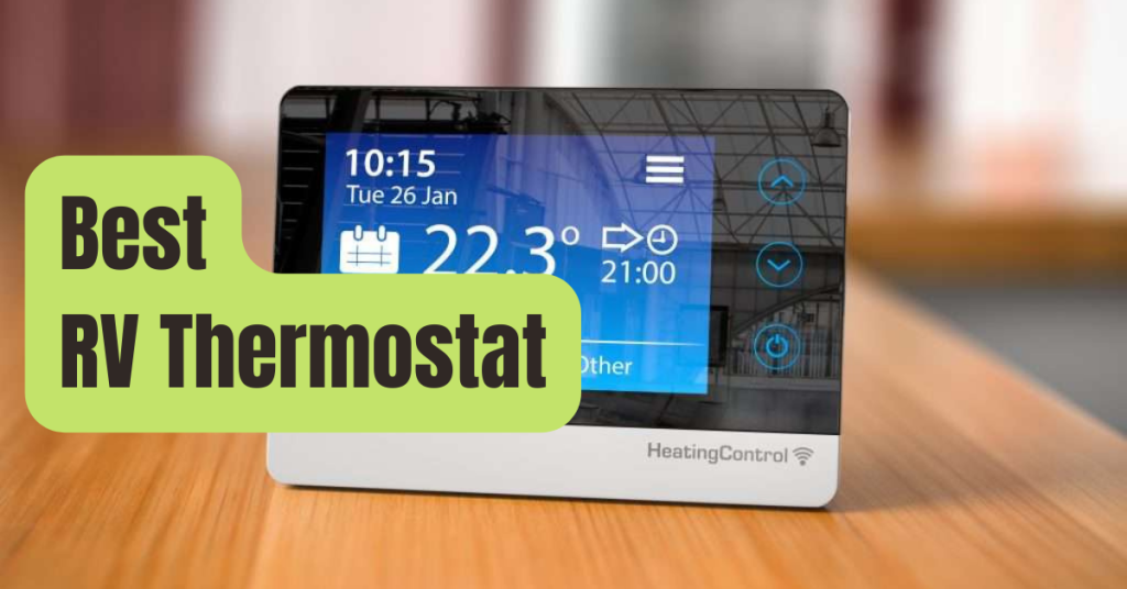
RV thermostats are identical to those used in conventional structures.
The function of coach thermostats in recreational vehicles, often known as RVs, is the same as that of thermostats in typical “stick-and-brick” homes.
They regulate the output of equipment used to manage the environment, most often furnaces and air conditioners.
Through the on/off switching of heated, cooled, and dehumidified air, they serve the purpose of maintaining a predefined temperature that is controlled via a digital or manual interface.
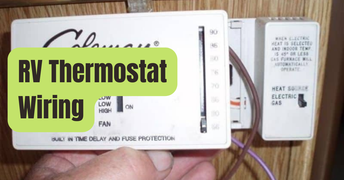
The same colored wire harness used in typical houses is utilized to connect RV thermostats to the equipment they regulate.
Step 1
Even though there is a typical schematic, neither manufacturer is subject to stringent industry standards, so make sure the customary wiring color-codes adhere to the thermostat that has to be connected and the preinstalled harness on the RV.
Consult the thermostat’s manual and any RV-specific material before drawing a wiring schematic and noting the color codes, functions, and terminal numbers.
Match the numerical codes of the terminals to their intended uses, then connect the proper color-coded wire to each terminal number.
Step 2
The outer casing of the thermostat is typically removed by pulling back one fastening screw from the face of the case’s bottom, then raising the case upward and outward.
Locate the wire connection terminals within the thermostat body, then remove all of the securing screws to provide enough room for the harness wires to pass through the terminal receivers.
Before removing the wires from an older-style “slider” device and replacing it with a digital update, create a schematic showing the original wiring and terminal pairs.
Step 3

Analyze the wiring to see if any wires are redundant.
For example, if your thermostat won’t be controlling an air conditioner, the wires designated for that function are redundant.
All cables that are not redundant should have a 1/4-inch layer of insulation removed from their ends using wire strippers.
Step 4
In accordance with your wiring schematic, connect the thermostat terminals with the stripped harness wires.
The connections are often created as follows: Normally, terminal 01 serves as ground and connects the 12-volt neutral system of the camper via a black or blue cable.
Usually receiving a red wire from the 12-volt coach system of the RV, terminal 03 is hot.
Typically, Terminal 05 accepts a yellow wire as the supply wire to the AC compressor.
The supply wire for an AC high fan speed is typically connected to terminal 06 and takes one of two green wires; the direction of the wires is immaterial.
The supply wire for the AC low fan speed typically goes to terminal 07 and uses the other of the two green wires.
The supply wire to the furnace typically enters at terminal 08 and takes a white wire.
Step 5
Each time a wire is entered, the proper terminal screw should be tightened.
Reposition the case and the case fastener when all the wires are firmly in place.